Research · Publication & note
Unidirectional Reflection from an Integrated “Taiji” Microresonator - Notes
Journal article
Published abstract
We study light transmission and reflection from an integrated microresonator device, formed by a circular microresonator coupled to a bus waveguide, with an embedded S-shaped additional crossover waveguide element that selectively couples counter-propagating modes in a propagation-direction-dependent way. The overall shape of the device resembles a “taiji” symbol, hence its name. While Lorentz reciprocity is preserved in transmission, the peculiar geometry allows us to exploit the non-Hermitian nature of the system to obtain high-contrast unidirectional reflection with negligible reflection for light incident in one direction and a significant reflection in the opposite direction.
Figures
© 2020 Chinese Laser Press. Source: A. Calabrese et al., Photonics Research 8(8), 1333-1341 (2020), DOI 10.1364/PRJ.393070. Reproduced on the author’s personal website under the rights retained in the journal’s copyright transfer agreement.
© 2020 Chinese Laser Press. Source: A. Calabrese et al., Photonics Research 8(8), 1333-1341 (2020), DOI 10.1364/PRJ.393070. Reproduced on the author’s personal website under the rights retained in the journal’s copyright transfer agreement.
© 2020 Chinese Laser Press. Source: A. Calabrese et al., Photonics Research 8(8), 1333-1341 (2020), DOI 10.1364/PRJ.393070. Reproduced on the author’s personal website under the rights retained in the journal’s copyright transfer agreement.
© 2020 Chinese Laser Press. Source: A. Calabrese et al., Photonics Research 8(8), 1333-1341 (2020), DOI 10.1364/PRJ.393070. Reproduced on the author’s personal website under the rights retained in the journal’s copyright transfer agreement.
© 2020 Chinese Laser Press. Source: A. Calabrese et al., Photonics Research 8(8), 1333-1341 (2020), DOI 10.1364/PRJ.393070. Reproduced on the author’s personal website under the rights retained in the journal’s copyright transfer agreement.
© 2020 Chinese Laser Press. Source: A. Calabrese et al., Photonics Research 8(8), 1333-1341 (2020), DOI 10.1364/PRJ.393070. Reproduced on the author’s personal website under the rights retained in the journal’s copyright transfer agreement.
© 2020 Chinese Laser Press. Source: A. Calabrese et al., Photonics Research 8(8), 1333-1341 (2020), DOI 10.1364/PRJ.393070. Reproduced on the author’s personal website under the rights retained in the journal’s copyright transfer agreement.
© 2020 Chinese Laser Press. Source: A. Calabrese et al., Photonics Research 8(8), 1333-1341 (2020), DOI 10.1364/PRJ.393070. Reproduced on the author’s personal website under the rights retained in the journal’s copyright transfer agreement.
© 2020 Chinese Laser Press. Source: A. Calabrese et al., Photonics Research 8(8), 1333-1341 (2020), DOI 10.1364/PRJ.393070. Reproduced on the author’s personal website under the rights retained in the journal’s copyright transfer agreement.
How to cite
Article access and reuse
The Version of Record is openly available from the journal. The Photonics Research copyright transfer agreement permits authors to reuse all or part of the work, including the publisher-formatted version, on their personal web homepage when the Chinese Laser Press copyright notice is retained. The figures below are the complete original compositions extracted from the article PDF and are reproduced with that notice.
Related publications



Research fields
Top-down
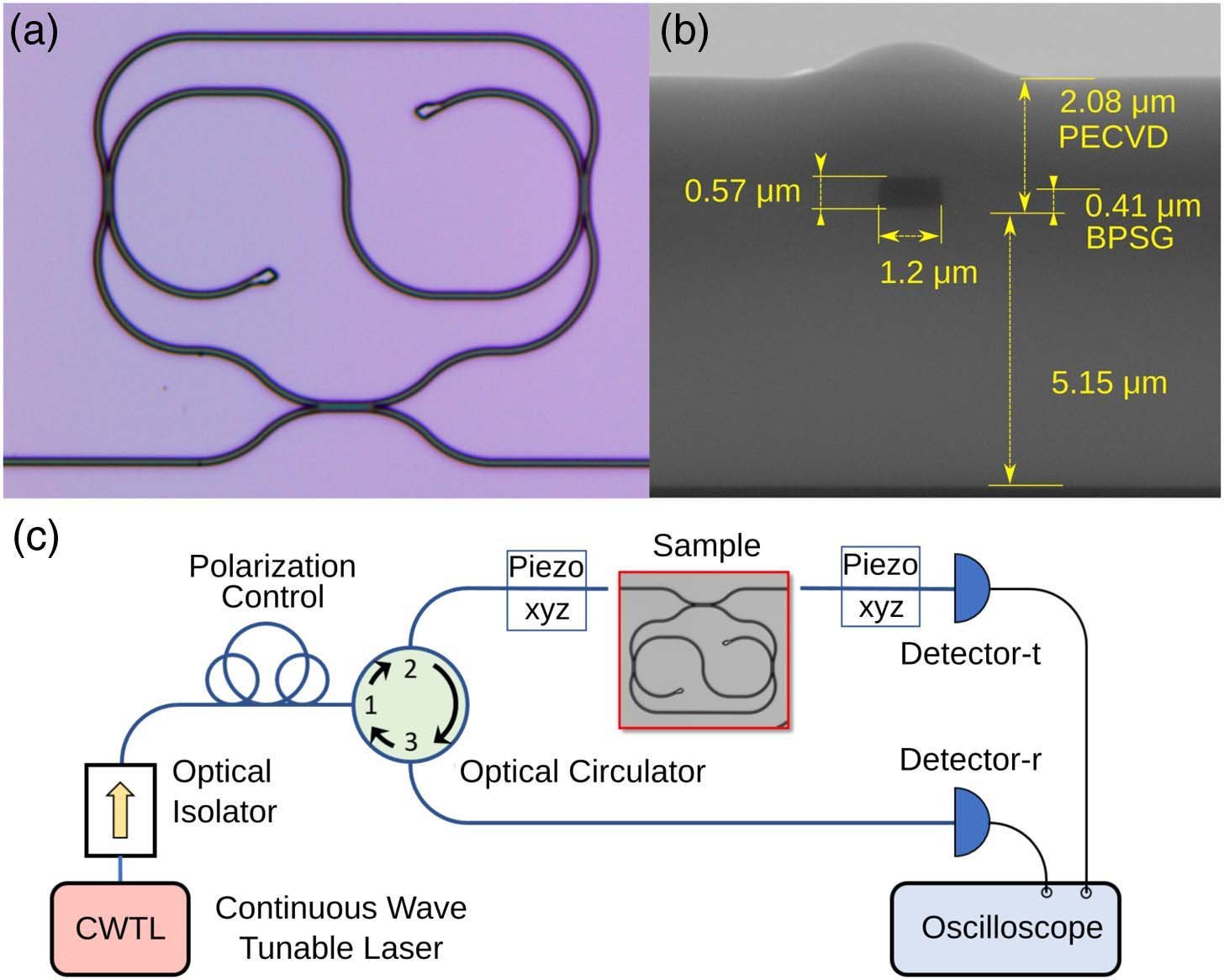
The Taiji resonator is fabricated as an integrated microring with an embedded S-shaped branch and a side-coupled bus waveguide. This patterned geometry selects the conversion between clockwise and counter-clockwise cavity modes while remaining compatible with an on-chip circuit.
Simulations & fits
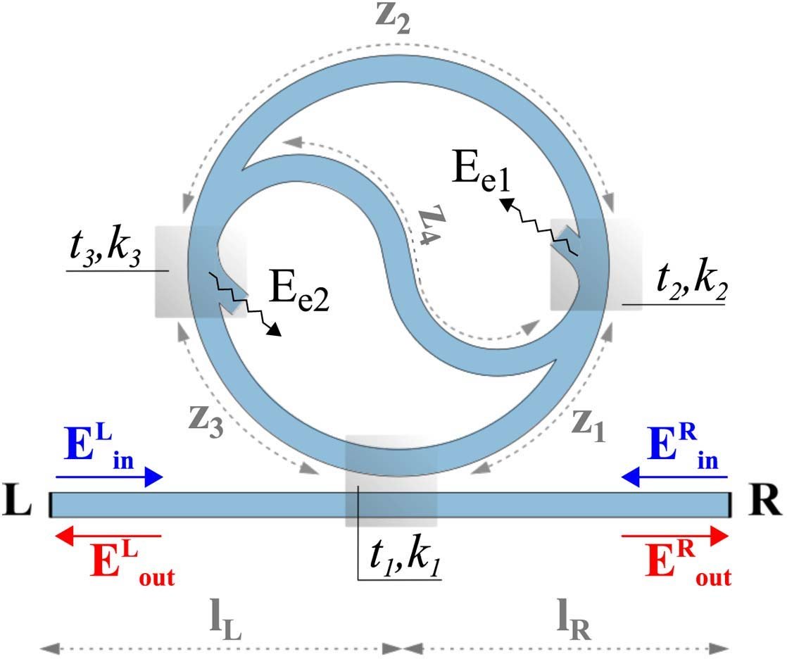
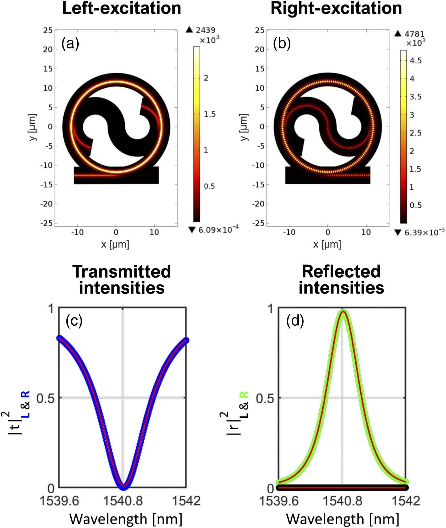
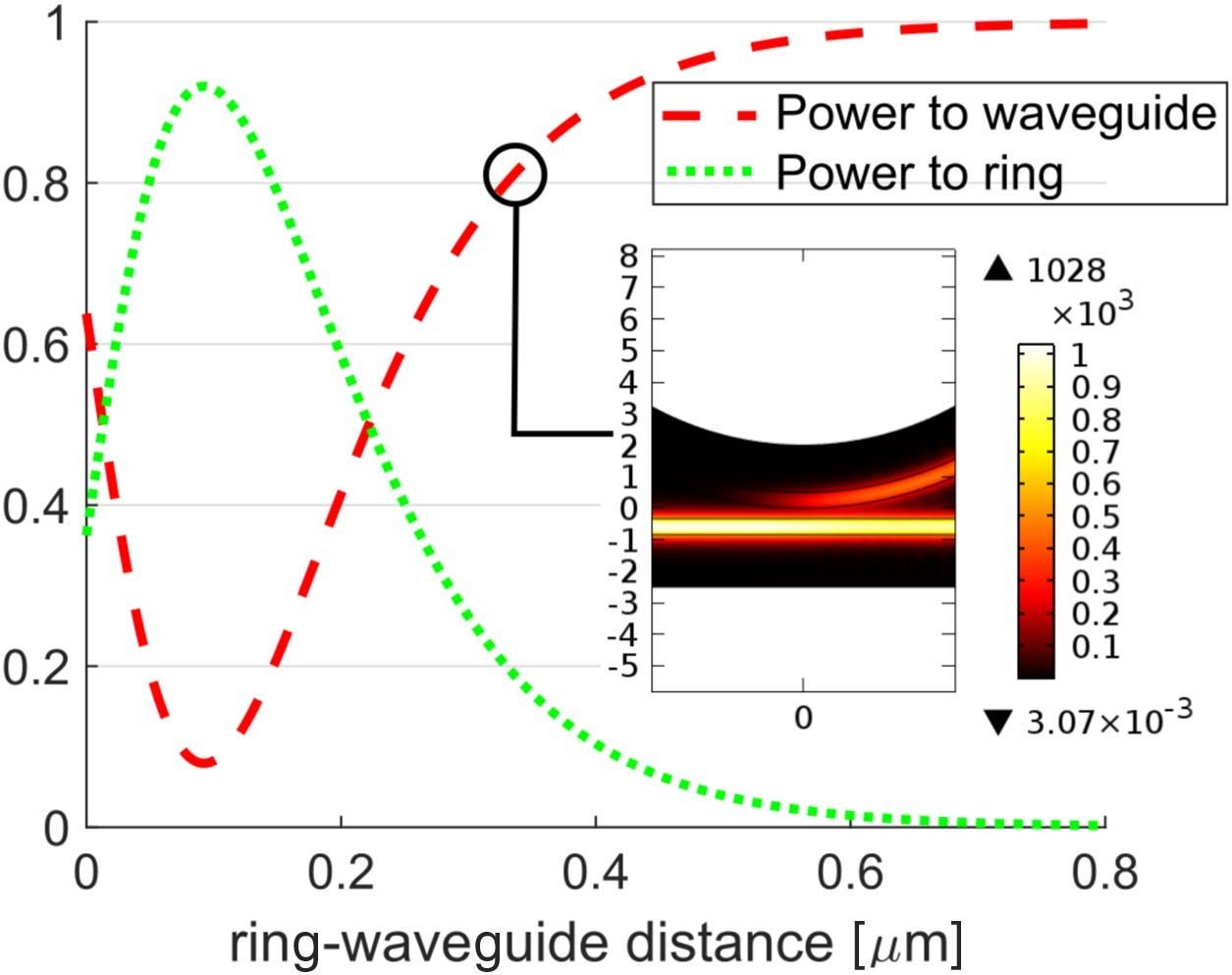
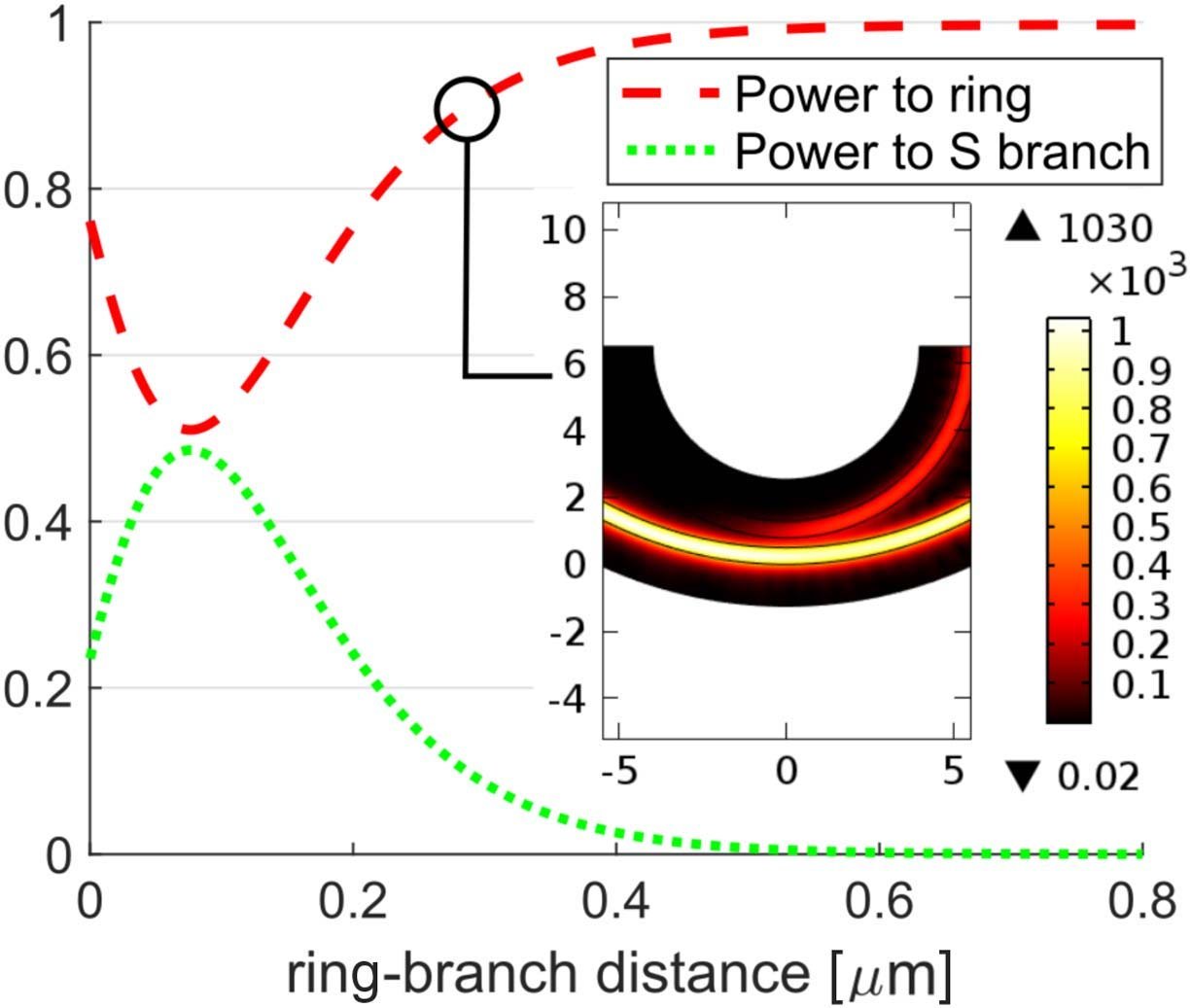
A transfer-matrix scattering model is validated against finite-element field simulations. Together they identify how the internal branch redistributes the circulating field and predicts direction-dependent reflection without violating reciprocal transmission.
Characterization
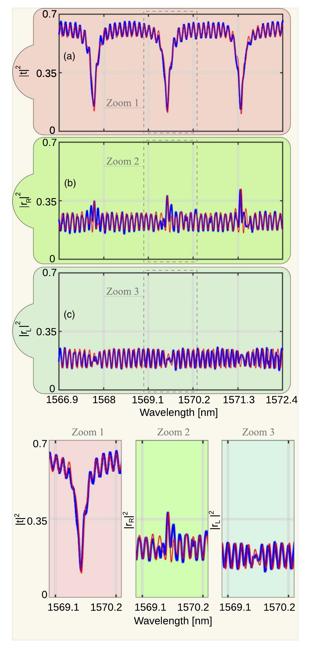
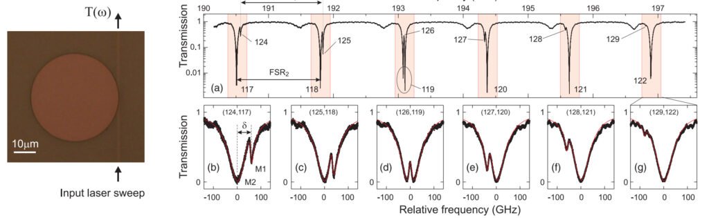
Optical transmission and reflection are recorded from both ends of the bus waveguide and compared with micrographs and cross-sectional SEM images. Measuring both launch directions distinguishes the resonator asymmetry from residual Fabry-Pérot fringes at the chip facets.
RESEARCH TOPICS
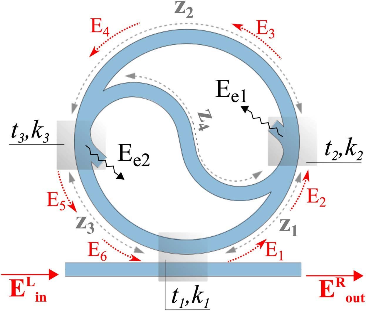
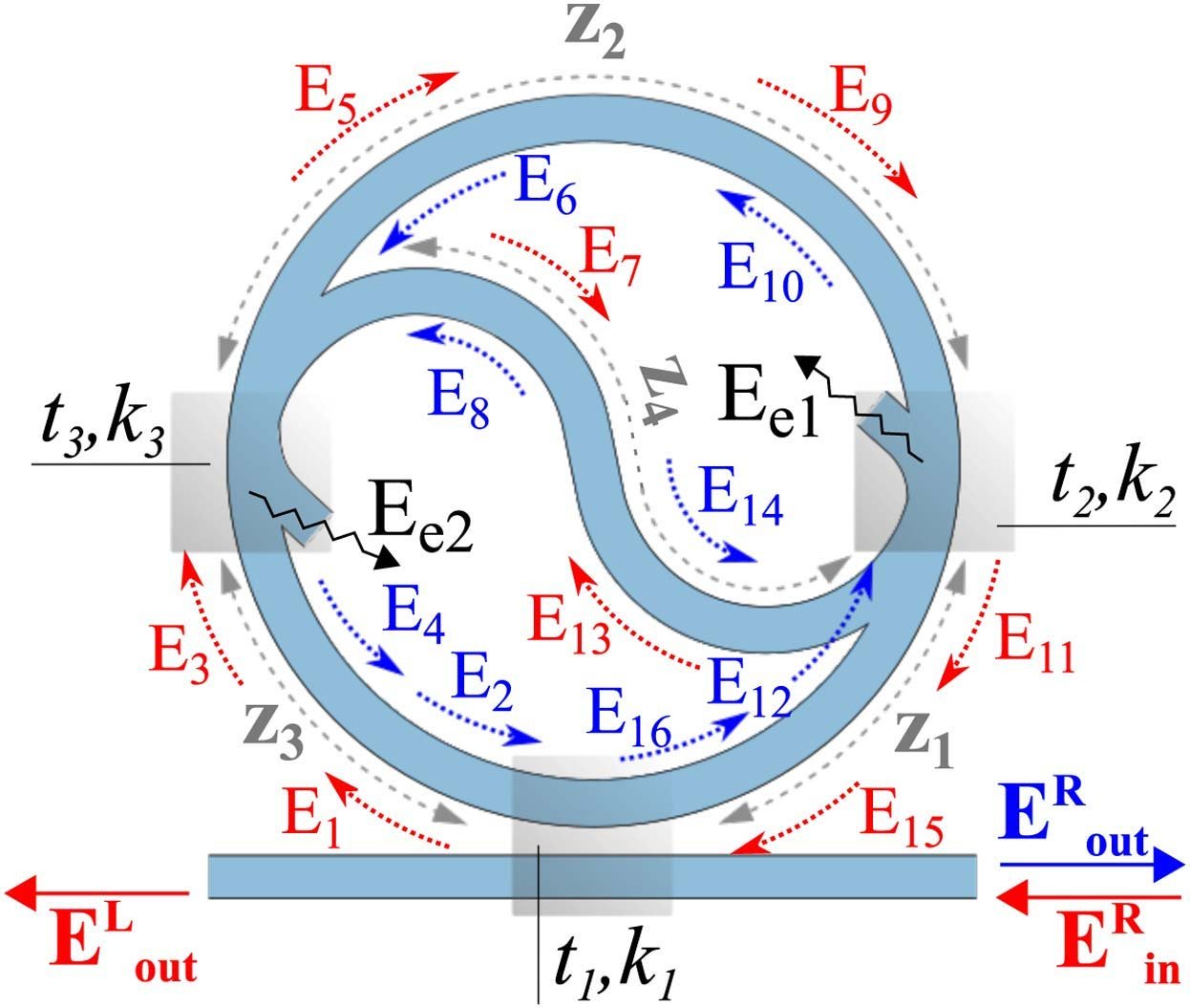
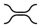 CouplingThe taiji device combines a racetrack resonator, a side bus waveguide and an S-shaped branch inside the ring. As Figures 6 and 7 make explicit, the structure can be decomposed into three evanescent beam splitters: one couples bus and ring, while two couple the ring to the ends of the S branch.
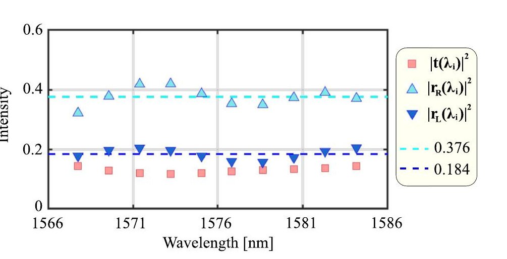
 InterferenceThe measured reflection contains more than the taiji resonance. Weak reflections at the two chip facets create a Fabry-Pérot background, and Figure 4(b) shows beating between those fringes and the field reflected by the resonator.
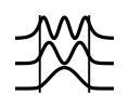 MultimodeHere the relevant pair of modes is not a set of unrelated transverse profiles but the two counter-propagating waves of the same ring resonance. The device thus uses controlled mode conversion to obtain direction-dependent output without claiming a linear optical isolator.
 ResonatorsExperiments, finite-element simulations and an analytical transfer-matrix description all show high-contrast unidirectional reflection: one incidence direction has a significant reflected resonance and the opposite direction nearly none. It establishes the taiji geometry as an integrated building block for directional reflection and for later nonlinear or laser implementations.