
Research · Publication & note
A Free-Space Interferometer for Phase-Delay Measurements in Integrated Optical Devices in Degenerate Pump-and-Probe Experiments
IEEE Transactions on Instrumentation and Measurement · Journal article · 1 December 2018
Abstract
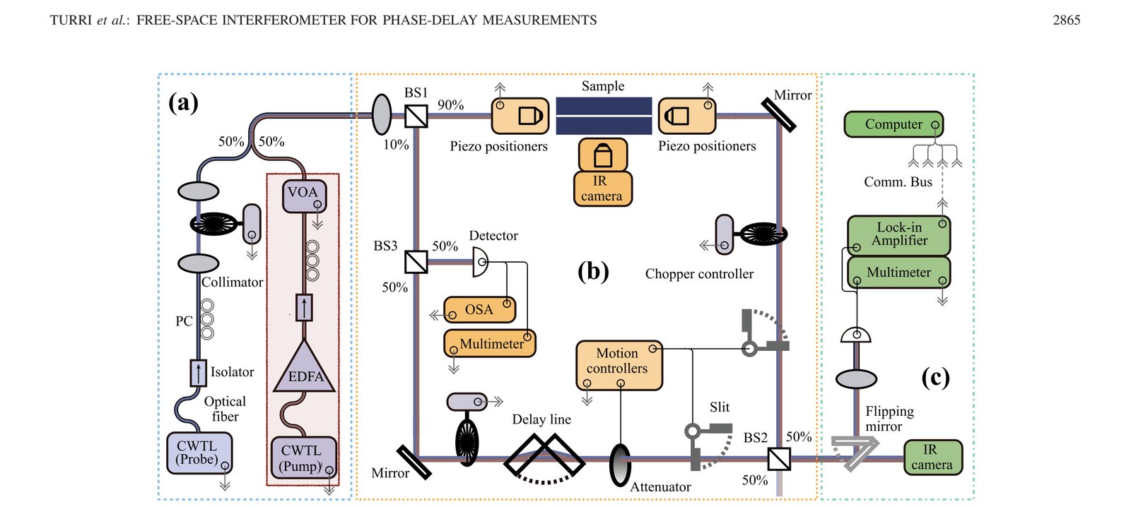
The authors report on a free-space interferometer for simultaneous phase and transmittance measurements of an optical signal in an integrated photonic circuit during degenerate pump-and-probe experiments. Differentiation of the weak probe signal from the strong pump relies on a lock-in amplifier. The interferometer shows high flexibility in terms of operating wavelengths, tested devices, and optical powers; it works with any integrated optical device provided with optical input–output channels; it can operate both with high input power (up to 100 mW at the sample input port) and low output power (<1 µW at the detection stage). Measuring both the transmittance and the phase of the optical signal allows using the phasor representation in the analysis. A dynamic operating mode allows to perform power and/or wavelength scan of the input signal, obtaining transmittance and phase spectra of the tested device. Remote control of the system and insulation from the external environment brings to more stable operating conditions. Characterization of the system properties with photonic-integrated structures (waveguide and ring resonator) is reported, with observed phase stability as high as 0.25°/min and average phase noise below 1°.
How to cite
Article access and reuse
This article was published under the standard IEEE copyright arrangement. IEEE permits authors to post the accepted article on their personal website when the DOI and the prescribed IEEE copyright notice are included; the local file reviewed for this catalogue is the IEEE-published Version of Record and is therefore not hosted here. The selected figures below are presented with the complete article citation and IEEE copyright notice. Further republication or redistribution requires permission from IEEE.
Figures
From F. Turri et al., IEEE Transactions on Instrumentation and Measurement 67(12), 2863–2870 (2018), DOI 10.1109/TIM.2018.2830845. © 2018 IEEE.
From F. Turri et al., IEEE Transactions on Instrumentation and Measurement 67(12), 2863–2870 (2018), DOI 10.1109/TIM.2018.2830845. © 2018 IEEE.
Research fields
Simulations & fits
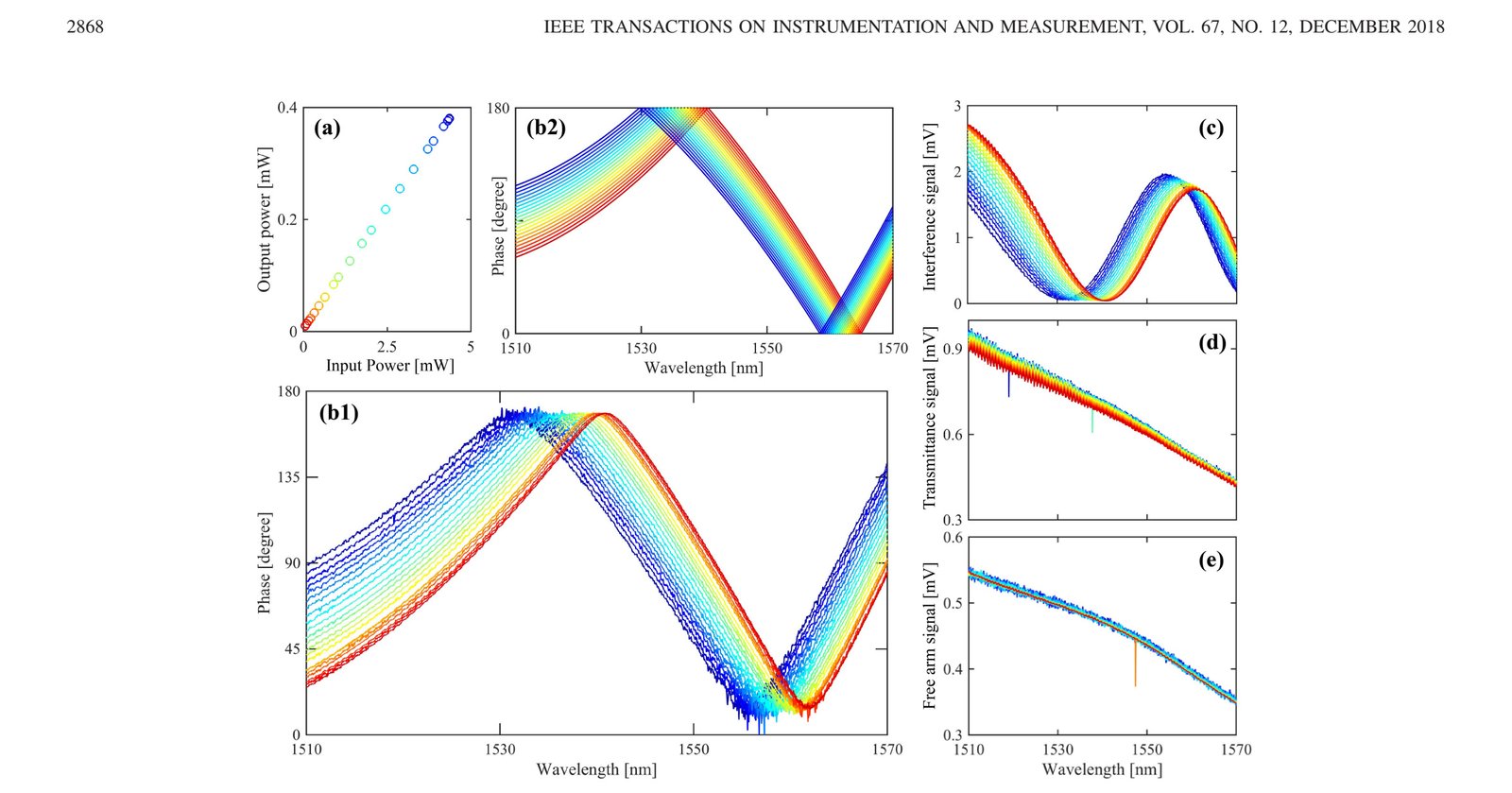
The phase-retrieval procedure reconstructs the probe's complex transmission from two interferometer acquisition modes and quantifies systematic phase errors. Thermal and nonlinear device responses can therefore be separated from drift and residual pump leakage in a degenerate experiment.
Characterization
The free-space Mach–Zehnder arrangement measures phase delay and transmittance simultaneously while a lock-in amplifier isolates the weak probe from a pump at the same wavelength. Tests on integrated devices establish its usable spectral range, stability and sensitivity under low- and high-power operation.
RESEARCH TOPICS
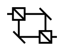 InterferenceThe free-space Mach–Zehnder reconstruction measures phase and transmission simultaneously, avoiding a phase inferred only from the depth of a resonance dip. The observed phase excursion identifies both measured mode families as undercoupled. Figure 8 quantifies the stability of the method: at low power the phase drifts about 0.25° per minute with roughly 1° average noise. These numbers define the smallest slow device-induced phase change that can be separated from interferometer motion and detection noise.
 NonlinearIn degenerate pump–probe operation, the strong pump changes the probe phase through the waveguide's intensity-dependent response. The measured evolution is attributed mainly to slow thermo-optic change in SiON rather than to a large instantaneous Kerr effect. Raising the pump to 1 W increases drift to about 1° per minute, consistent with heating and thermal expansion of the optical path. The experiment therefore provides a caution for nonlinear measurements: a stable-looking spectral shift can still contain a time-dependent thermal phase.
 SetupsFigure 2 divides the apparatus into preparation, interferometer and detection stages. Tunable pump and probe lasers, an EDFA, polarization controllers, attenuation and probe chopping feed the integrated sample. The emerging probe is recombined with a reference arm and detected with a germanium photodiode, while synchronized remote control scans wavelength and records both phase and transmitted intensity. This modular arrangement makes it possible to measure weak phase delays in an integrated component without losing the spectral information needed to identify its coupling regime.